Welcome
You have reached the OLD Control Panel page
For the New Control Panels, Click Here
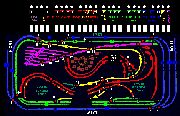
My first railroad was on two 4 x 8 sheets of plywood (4 x16) with two lines, the inside line and the outside line. When that became boring, I added two more lines around the garage making a total of 4 lines.
I made a control panel with each line a different color, and used atlas switches for the blocks as shown at the top of the panel. Click for enlargement

This layout and control panel were never finished because I came to the conclusion that a one car garage was too small, and tore everything down including the wall between the two garages, and started over in the new improved two car garage
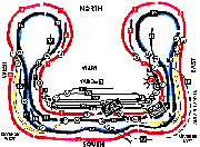
I started with an actual layout with the blocks and turnout numbers. click the actual layout below for enlargement.

This control panel, like the old one was too confusing to follow the loops to find the switches and blocks and by the time I was going to add all the lights and switches it was going to look way to complicated and hard to figure out. To simplify things I did what the pros do, I unwrapped the loops into straight lines to make it easier to see the path and turnout directions of the lines. Since I had two lines, I made two paths, one on top of the other, and where the two lines connected, I made thinner lines as shown on the panel below
Click the control panel below for enlargement

Here's some info on the new control panel
I used 22 Gauge (not 24 gauge) solid (not stranded) 4 color telephone wire, available in 50 foot rolls at Home Depot for about $20.
I used Peco brand turnouts, turnout swithes, and turnout accessory switches.
I used Kadee (they're the smallest) momentary red and green pushbutton switches. They're so small you can't solder them but they supply an alternate method of attatching the wires.
I used double pole double throw mini toggle switches from Miniatronics for the track blocks.
I used red and green "grain of wheat" bulbs from Miniatronics for the control panel . Don't use LEDs because they're a pain in the butt. You need to solder a resister on one end only, which cuts power, and the electricity can only go through one way. A bulb, on the other hand is already 12 - 16 volts and works with the electricity going through either way.
Click for the lights and turnout switches wiring schematic below for enlargement.

Coming Soon:
a similiar schematic for wiring the blocks and their corresponding control panel lights.


